Geiger Müller Design Notes
3. Proportional Counter Design
The proportional Counter is located at the top of the CubeSat, near the antenna section, Figure 3.1. The Geiger Müller tube is an Energy Compensated LND71210 [1], which has been vacuum tested down to 14×10-6 Torr. This tube has a starting voltage of Vs = 350 V and a recommended operation range of 450 — 650 V for operating in Geiger Counter mode. The sweet spot for the Proportional Counter was found to be around 375 V, by experimenting with a variable power supply and sensing circuit (cf., Figure 1.2-Left), while observing the tube's response to cosmic rays. The Centr☢nic's [2] Gieger Müller Tubes guide contains detailed information on Geiger Müller radiation counters, which has been invaluable while designing the Proportional Counter Subsystem.
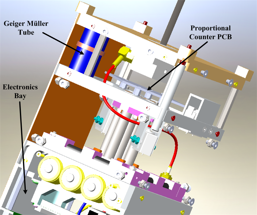 |
| Figure 3.1: Location of Geiger Müller Tube for Proportional Counter. |
Figure 3.2 shows the prototype proportional counter circuit that was designed for the payload subsystem. The power supply was adapted from a Geiger Müller Kit [3] and the sensing circuit was designed in accordance with the notes in Section~\ref{ap:gcdesign}. A 3.3V Zener was placed on the output of the sensor to protect electronics bay's 3.3V input AD7680 SPI-ADC, to be interfaced to the Command and Data Handling Q6 Processing Board. Finally, a line-filter capacitor was added to reduce flyback-noise on the main 5V line.
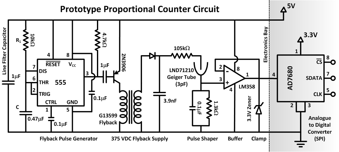 |
| Figure 3.2: Proportional Counter Circuit. |
Figure 3.3 shows the prototype circuit mocked up on a breadboard. The circuit was assembled section by section and the waveforms observed so as to ascertain the overall response of the circuit.
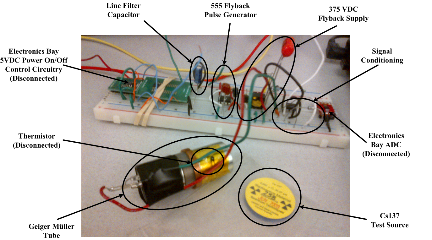 |
| Figure 3.3: Prototype Breadboard Layout of Proportional Counter Circuit. |
Figure 3.4 shows the noise on the 5\,V line with and without a 1μF capacitor. It was found that the noise was reduced by roughly one-half per decade increase in capacitance. The final circuit used a 2.2μF surface mount capacitor, the largest practical (COTS) space-qualified capacitor size.
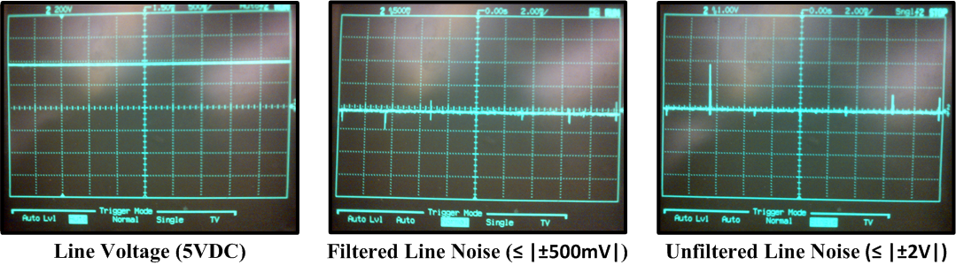 |
| Figure 3.4: Proportional Counter Circuit 5 VDC with and without 1μF Line Filter Cap. |
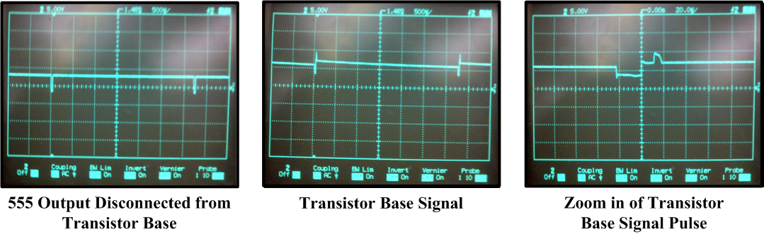
Figure 3.5 shows the flyback pulse generator signals from the 555 timer circuit [4]. The dips in the pulse train correspond to the transistor being turn on momentarily. The dips are roughly 28μs in duration, reoccurring roughly every 3.2ms.
 |
| Figure 3.5: Proportional Counter Circuit 555 Timer Flyback Pulse Generator Signals. |
The frequency for this type of circuit is typically governed by [4]
 . . | (3.1) |
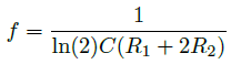
However, here, R2 is replaced with a wire, and so the dips are indicative of the propagation delay times within the chip. Figure 3.6 shows the signal across the flyback transformer.
 |
| Figure 3.6: Proportional Counter Circuit Flyback HV Circuit Signals. |
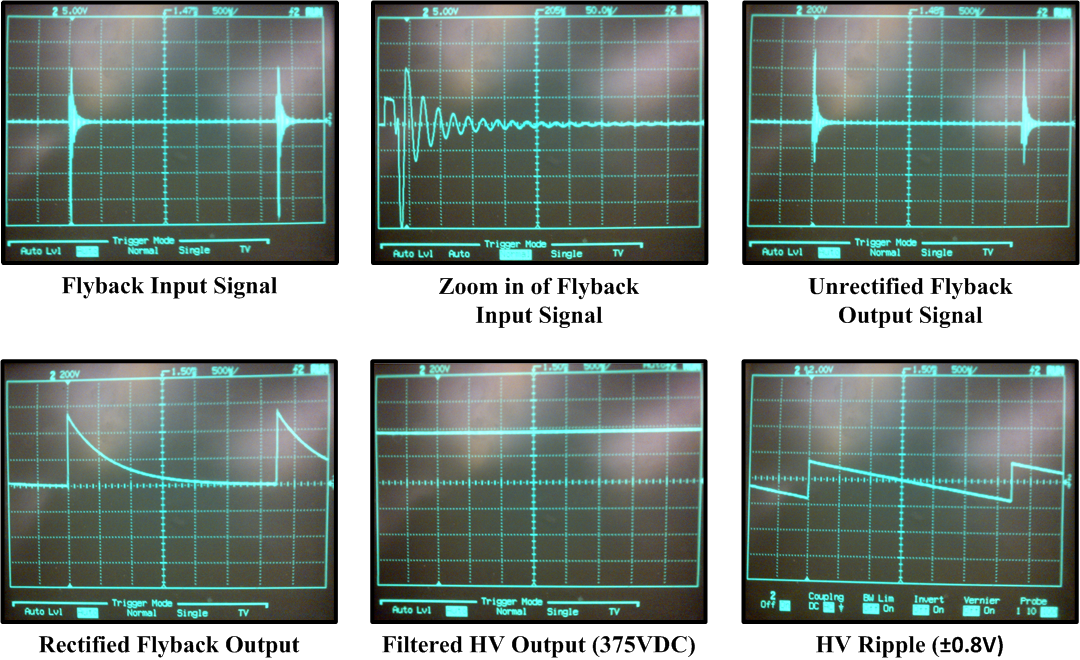
This circuit uses a flyback transformer whose H-field collapse provides a significant flyback response as the coil is momentarily energized from the switching transistor, Figure 3.7.
 |
| Figure 3.7: Converter Transformer Modalities [5]. |
As a small voltage-kick corresponds significant flyback response within the primary and secondary of the transformer; thus requiring a smaller turns ration that typical transformers. The damped oscillations are due to the self-field collapsing decays are energy is dissipated due to the transformer's intrinsic resistances and capacitances. Also shown in Figure 3.6 are the rectified and smoothed waveforms. Finally, Figure 3.8 shows the output signal from the cathode side of the Geiger Müller, the buffer circuit, and the final signal at 3.3V zener diode.
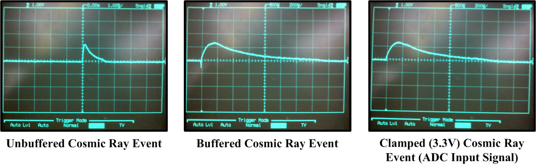 |
| Figure 3.8: Proportional Counter Circuit Cosmic-Ray-Signal Conditioning (i.e., without Cs137 Test Source). |
A quick calibration can be performed on the circuit using Equation 1.3; a la, Figure 1.2 and Figure 3.9. For our prototype board, Figure 3.3, using a Cs137 source and an oscilloscope, we find peaks heights of 0.2V and 1.4V corresponding to energies of 0.5MeV and 1.2MeV, respectively.
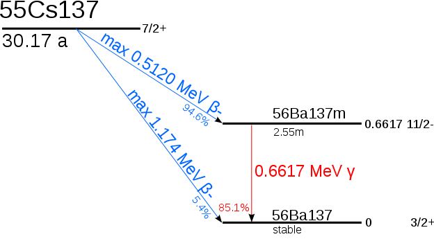 |
| Figure 3.9: Cs137 Energy Spectrum [6]. |
This gives us the relationship,
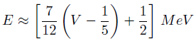 . . | (3.2) |
See the Arduino Source Code section for detailed notes on the SPI interface and software tools required for spectral analysis developed using and Arduino Uno.
References:
[1] LND INC 71210 Energy Compensated Geiger Müller (Gm) Tube Data Sheet.
[2] Geiger Müller Tubes, Centr☢nic.
[3] Geiger Counter Kit without GM Tube, Item Number G18410, US, The Electronic Goldmine, PO Box 5408, Scottsdal, AZ 8521.
[4] LM555 Single Timer Datasheet, Fairchild Semiconductor Corporation, Rev. 1.0.4, 2011.
[5] Switched Mode Power Supplies, Chapter 2, Introduction to Power Semiconductors, Power Semiconductor Applications, Philips Semiconductors.
[6] Caesium-137 - Wikipedia, the free encyclopedia.
___________Last Updated: 8:14 PM EST Oct. 30th, 2014