Geiger Müller Design Notes
1. Proportional Counter Theory in a Nutshell
Figure 1.1 shows proportional counter theory in a nutshell. The main component is a gas filled Geiger Müller tube with a conducting outer cathode wall and a long anode wire down the middle, held at a high potential. As an ionizing particle passes through the tube it creates an ion trail which is dissipated into the surrounding circuitry as an electrical pulse.
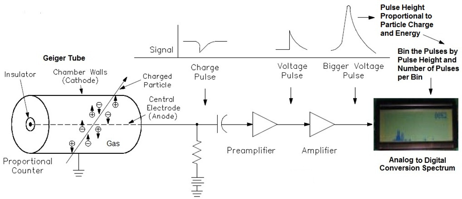 |
| Figure 1.1: Proportional Counter Theory in a Nut Shell. (Figure adapted from Gedeon [1].) |
The electrical pulse can be pulled off either the anode, Figure 1.1, or the cathode, Figure 1.2, of the tube (for a detailed discussion about the pros and cons see Centr☢nic's Geiger Müller Tubes guide [2]).
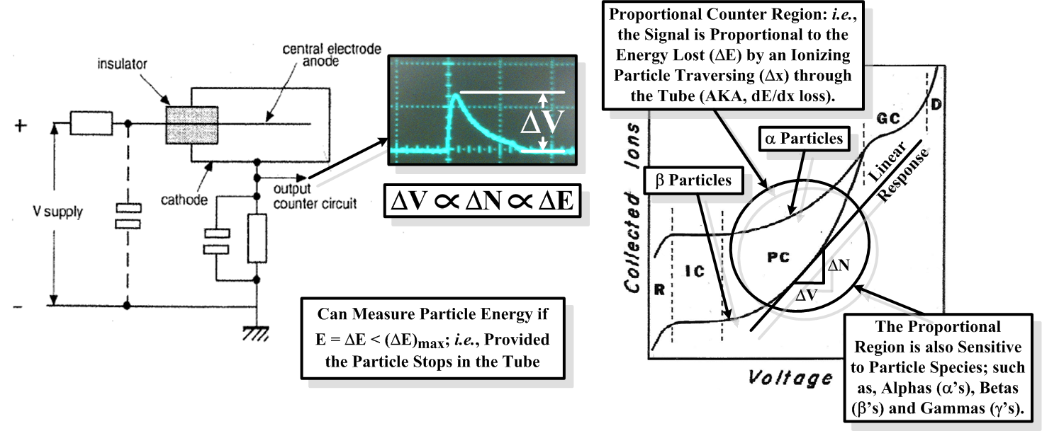 |
| Figure 1.2: Cathode Method of Signal Capture for a Geiger Müller Tube (left; adapted from Centr☢nic [2]) in Proportional Mode (right; adapted from Fernow [3]). |
If the voltage across the tube is set appropriately, then the output pulse-height from the tube will be proportional to the energy deposited by the particle traversing the tube (AKA, the dE/dx loss of the particle): i.e., the magnitude of the induced voltage signal goes as,
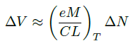 (cf., Figure 1.2.), (cf., Figure 1.2.), | (1.1) |
where e is the fundamental electric charge, ΔN is the number of created ion pairs, M is the multiplication factor, C is the intrinsic capacitance of the tube, and L is the length of the tube (see chapter 9 of Fernow [3] for a more detailed theoretical discussion). The multiplication factor is dependent on gas mixture, pressure, P, temperature, T, and applied voltage. For our specific application, the tube's operating temperature is expected to vary, and, as such, its properties will need to be characterized as a function of temperature (cf., Figure 9.5 of Fernow).
In proportional mode the number of created ion pairs is directly proportional to the energy loss of an ionizing particle as it traverses the tube: i.e., ΔN ∝ ΔE=∫tube(dE/dx) dx … and so we have the relation
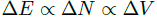 , , | (1.2) |
which completes our description of Figure 1.2. (… well, OK, dE/dx is also a function of particle species.) So our tube response is experimentally determined by fitting
 , , | (1.3) |
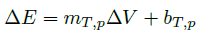
with slope, mT,p and intercept, bT,p, for fixed temperature, T, and particle species, p [1, 3]. In addition, if the particle is stopped in the tube then
 , , | (1.4) |
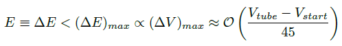
As ΔE is path dependent, there is a spread in the spectrum due to the geometry of the tube. Therefore, if we are trying to measure the energy of a particle, E < (ΔE)max, we must take into account the path lengths, the Δx's, of the loci of rays passing through the intersection of the bisecting plane of the tube: i.e., in cylindrical coordinates, E = ΔE(φ,z)tube ≠ "Constant." That said, this problem can be remedied by adding bits of material around the tube, such that, ΔE(φ,z)material + ΔE(φ,z)tube = "Constant." Geiger Müller tubes with this property are called energy compensated tubes. (Note that such tubes also have an energy window, (ΔE)min < E < (ΔE)max, due to the cutoff energy of the material, (ΔE)min, below which the particles are stopped.) Figure 1.3 shows an example of a radiation pattern for an energy compensated tube.
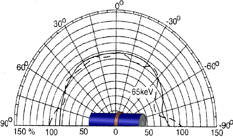 |
| Figure 1.3: Example of E(φ) for an Energy Compensated Geiger Müller Tube. (Figure adapted from Centr☢nic [2].) |
References:
[1] G. Gedeon, Radiation Detectors for Industrial Facility Systems (Course No: D06-001), CEDEngineering.Com, Continuing Education and Development, Inc., 9 Greyridge Farm Court, Stony Point, NY 10980.
[2] Geiger Müller Tubes, Centr☢nic.
[3] R. Fernow, Introduction to Experimental Particle Physics, Cambridge University Press, 1986.
___________Last Updated: 8:14 PM EST Oct. 30th, 2014